|
|
Updated: Wednesday, 16 November 2011 |
|
|
|
Updated: Wednesday, 16 November 2011 |
|
|
The Murphy
Corner-Line-Array An Open Loudspeaker Design Project by John L. Murphy Physicist/Audio Engineer |
|
5. Array Test Results 6. Line References/Links |
7. Project Log 8. MCLA Discussion Thread |
||
|
5. Array Test Results |
|||
|
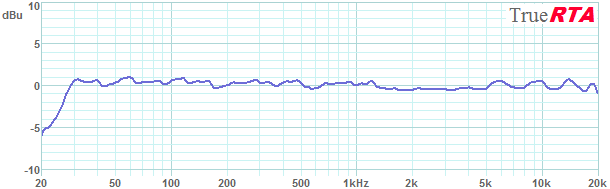
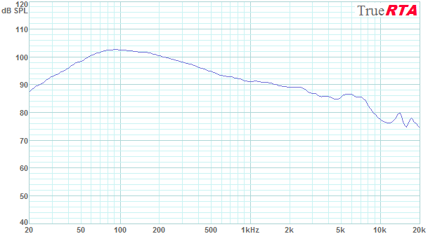
Equalized In-Room Frequency Response Here are the current frequency response measurements as of 3Oct09. Each measurement below is an average of the Left and Right systems in-room measured response. Each of the Left and Right measured responses consists of an average of 16 unsmoothed responses measured in the listening area over a range from 1 to 3 meters from each array. The final average is smoothed just one time if smoothing is specified. The unsmoothed average is an average of completely unsmoothed data. These responses represent the array with my best equalization to date. Note that the responses are shown at a high resolution with 1 dB per division on the vertical scale. Figure 5-1 shows the MCLA measured spatial average frequency response with 1/3rd octave smoothing. This is what would typically be given as the measured response if this were a commercial loudspeaker. The frequency response is seen to be within +/- 1 dB from 28 Hz to 20 kHz.
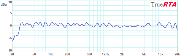
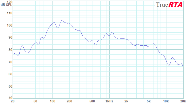
Figure 5-2 shows the same measured frequency response as above but this time with more conservative 1/6th octave smoothing. The frequency response is seen to be within +/- 1.5 dB from 28 Hz to 20 kHz. This 1/6th octave smoothed response probably corresponds most closely with what you would actually hear from the system as 1/6th octave corresponds to the "critical bandwidth" of human hearing in the range above 1 kHz. Below 1 kHz the critical bandwidth gets progressively wider as the ear becomes less discerning and greater smoothing could be used without misrepresenting what we would hear. So above 1 kHz we don't want to use any more than 1/6th octave smoothing. Below 1 kHz the 1/3rd octave smoothed response of Figure 5-1 above is more representative of our ear's response.
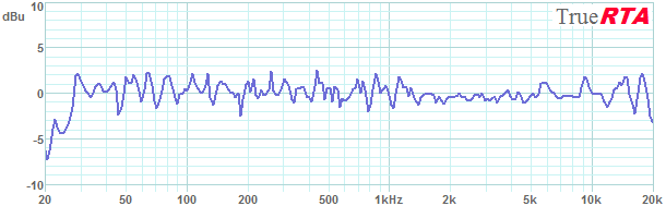
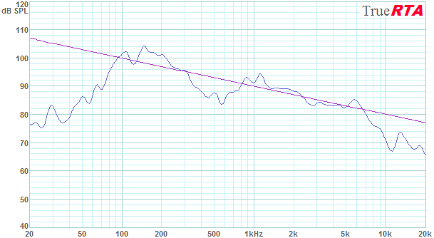
Figure 5-3 shows the completely unsmoothed spatial average response of the MCLA system. The unsmoothed response is seen to be within about +/- 2.5 dB from 28 Hz to 20 kHz. Keep in mind that loudspeaker manufacturers rarely (if ever) show this high level of detailed data for their commercial loudspeaker systems.
Un-equalized In-Room Frequency Response
The equalized frequency responses shown in the previous section show the arrays with their equalization switched in as they are normally used. In this section I will show the un-equalized frequency responses in order to understand the required components of the equalization. It is reasonable to ask what frequency response we expect from the arrays. Based on my understanding of line arrays I expect to see the half space response of the driver modified my the -3 dB per octave slope resulting from the effect of array. There will also be some lumps and bumps resulting from the finite spacing of the drivers. The 3 dB per octave boost in the bass from the array effect may not continue all the way to 20 Hz due to the finite length of the array. Remember, the reflections taper off due to finite absorption of the room surfaces so the bass build is expected to be limited. In Figure 5-4 below we see the single driver's hybrid measured response along with a -3 dB per octave reference slope. If we tilt the single driver response the -3 dB per octave we expect the array to add then we should get a response similar to what we expect from the raw (un-equalized) array. Just for fun I'll add the two responses shown here to get some idea of a "predicted" array response.
Summing the two responses shown in Figure 4-14 gives the "predicted" response for the array shown in Figure 5-5.
In order to restore the flat response of the single driver we would need to equalize the above response with a 3 dB per octave rise. Then, in order to extend the bass response to 30 Hz we would need bass equalization. The bass equalization might take the form of a "Linkwitz Transform" circuit to precisely create a new target response or could be achieved with a general purpose digital EQ such as I am doing. Finally, here in Figure 5-6 is the un-equalized measured response of the two array prototypes. This response is an average of the two measured responses for each array in-room. Each individual array was measured at sixteen locations around the listening area at a distance from 1 to 3 meters. The individual array responses were smoothed at 1/6th octave before the two were averaged. The similarity to the predicted response is notable, especially regarding the overall -3 dB per octave slope of the array. The low frequency corner is expected to be slightly different than the single driver response because the single driver was measured in a 0.1 cubic foot closed box. The array has .045 cubic feet per driver so the array has a higher closed box Q(tc) than the single driver test system. This results in a higher closed box Q for the array versus my single driver data.
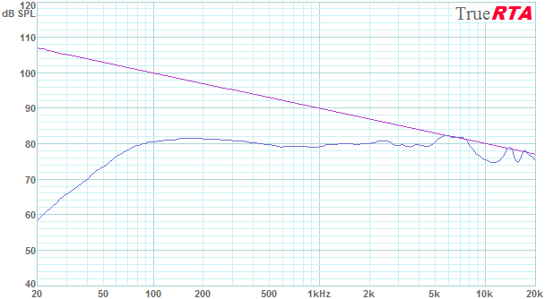
The frequency response in Figure 5-6 was measured with a drive voltage of 2.309 Vrms which corresponds to 1 Watt into the array's nominal impedance of 5.33 Ohms. Note the very large build in efficiency in the 100 to 200 octave where the array has an efficiency exceeding 100 dB SPL for 1 Watt over the 1 to 3 meter range. With the array receiving an input of 1 Watt each driver was being driven at 1/24 Watt or .042 Watts. While producing over 100 dB SPL in the 100-200 Hz bass range the drivers are just being tickled a bit with 42 milliwatts of drive. Operating the array at 100 Watts (or just over 4 Watts per driver) would add 20 dB to the above levels. The usual 1W/1meter sensitivity specification of a typical speaker is not appropriate for an array. Instead we would have to indicate sensitivity at a specific frequency or preferably, just show sensitivity a graph as above. Figure 5-7 shows the measured response along with a -3 dB per octave slope for comparison.
All in all the arrays achieve a frequency response much like what is
expected based on the single driver measurements. The essential components
required of the corrective EQ are a 3 dB upward slope (a blue filter) and EQ
to extend the bass response. In practice the final EQ is best achieved by a
measuring the response and adjusting the EQ a few times in succession until
a sufficiently flat response is obtained.
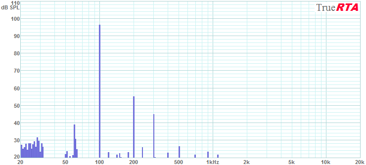
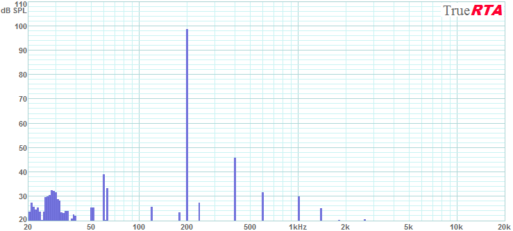
Distortion Performance The spectrum of the completed array was measured with 1 Watt at 1 meter at key frequencies in order to evaluate its distortion performance. The only significant distortion seen was at 2nd, 3rd and 5th harmonics. The relatively benign 2nd harmonic dominates the distortion makeup below 1 kHz. Harmonics above the 5th are very well behaved as they continue to descend in level. Figure 5-8 shows the spectrum from one array driven at 2.31 Vrms (1 Watt into 5.33 Ohms) with a 100 Hz sine wave. The array creates a very efficient 96 dB SPL for 1 Watt/1meter. The 2nd harmonic, 200 Hz is measured at 41 dB below the 100 Hz fundamental for a distortion level of 0.9%. The 3rd harmonic is -51 dB with respect to the fundamental for a level of 0.3%. The 5th harmonic at 500 Hz is even lower at -70 dB or 0.03%. Higher harmonics continue to descend in level and vanish into the noise floor. The line at 60 Hz is just ambient noise.
Next in Figure 5-9 we see the array at reproducing a 200 Hz sine wave at an incredible 98 dB SPL with only 1 Watt of input. The distortion is quite low compared to any loudspeaker I've measured. The 2nd harmonic at 400 Hz is down 52 dB or 0.25% distortion. The 3rd harmonic (600 Hz) is at -66 dB or 0.05% distortion. The higher harmonics continue to descend in level even further.
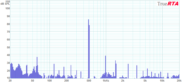
Note the results above are for just 1 Watt into the array or just 1/24th of a Watt per driver. If the array were driven at 24 Watts each driver would then get 1 Watt and the output of the array would increase by 14 dB. This means that at 200 Hz a single array would generate 98 + 14 = 112 dB SPL with each driver at 1 Watt(24 Watts total input). Yet the distortion would be similar to a single driver driven at 1 Watt, that is, very low. How many other speakers do you know that can generate 112 dB at 200 Hz with distortion on the order of 0.2%? The array's performance at 500 Hz is shown in Figure 5-10. Output has fallen to 86 dB SPL for 1 Watt at 1 meter but the distortion continues to be quite low. The 2nd harmonic is at -47 dB or 0.4% distortion. The 3rd harmonic is at -53 dB or 0.2%. The 5th harmonic is at -58 dB or 0.13%. Higher harmonics descend further in level.
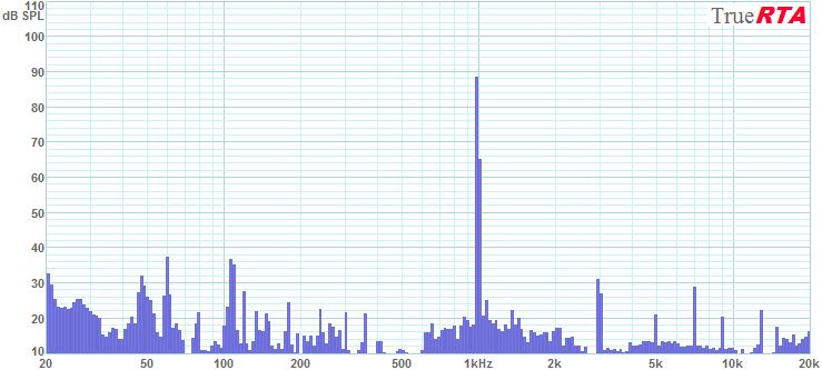
Figure 5-11 shows the array at 1 kHz with 1 Watt of input creating 89 dB SPL. The 2nd harmonic is absent with the 3rd harmonic (3 kHz) at -57 dB (0.14% distortion) compared to the fundamental at 1 kHz. The 5th harmonic is at -67 dB or 0.04%. The 7th harmonic pops up to 0.1% but the 9th and higher continue the fall to lower levels.
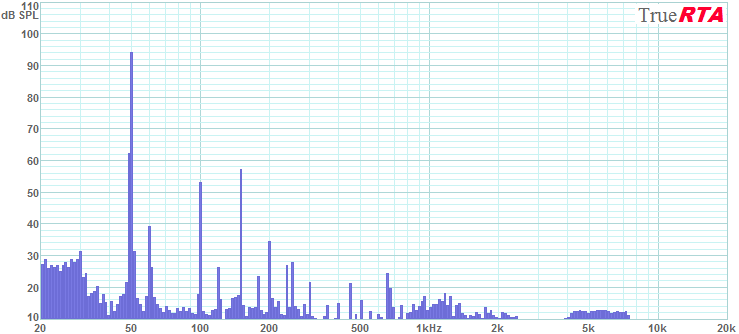
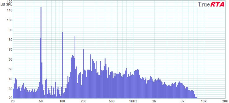
For a look at the low bass performance here in Figure 5-12 below is the performance at 50 Hz for 1 Watt at 1 meter. The output level is still quite high at 94 dB SPL indicating the strong low frequency boost from the combination of the 24 drivers and the corner placement. Remember even though the array is putting out 94 dB SPL with 1 Watt it has a power handling capability of 480 Watts or 27 dB greater than the 94 dB SPL we see here. This suggests the array could generate 121 dB SPL at 50 Hz at its max rated power of 240 Watts. There is no shortage of low frequency output capability. At 50 Hz the 2nd harmonic is -41 dB down for 0.9% distortion. The 3rd harmonic increases to -37 dB or 1.4% distortion. Higher harmonics are much lower in level.
As a low frequency stress test I tried to drive the array to 10% distortion at 50 Hz. This is one measure of the maximum operating level of a speaker in the low bass range. Figure 5-13 shows the array operating at the highest level I could generate before the everything in the room started vibrating loudly. The system reached 113 dB SPL at 50 Hz with 65 Watts of drive level (18.7 Vrms into 5.33 Ohms). The dominant distortion is 2nd harmonic at -26 dB or 5% distortion. The 3rd harmonic is at -29 dB or 3.5%. The 5th harmonic was only at -48 dB or 0.4%. This is excellent high SPL low bass performance! A single array can drive the ROOM to the limit of what it can take with just 65 Watts at 50 Hz. At the highest levels a person (or room) can stand (113 dB SPL in this case) the distortion does not exceed 5% at 50 Hz.
The distortion test show a speaker system capable of very high output levels with very low distortion. In all cases the distortion is dominated by the low order harmonics and is frequently dominated by the (relatively benign) 2nd harmonic. Distortion should not be a concern at even the highest sound levels...even for a single enclosure. The distortion tests confirm what I heard while stress testing a single drive unit with my guitar. Playing my telecaster electric guitar through the corner line arrays provides a pristine clean sound in the room at any level I wish. If I crank it up they can really rock without any hint of stress. Palm muted guitar delivers an awesome thump. Bass guitar likewise sounds fantastic through the arrays. When rehearsing with my buddy I see the average SPL easily breaking 90-95 dB SPL with peaks up to 110 dB SPL. I hear no sounds of stress from the system and my small power amp remains cool to the touch. Microphone feedback is less of a problem with the new speakers as we seem to be able to get more level from the vocals before feedback sets in.
|
|||
|
|
|
True
Audio Home Page | Catalog |
Tech
Topics | Audio Links |
Book
Store Your comments are welcome at webmaster@trueaudio.com |