|
|
Updated: Wednesday, 16 November 2011 |
|
|
|
Updated: Wednesday, 16 November 2011 |
|
|
The Murphy
Corner-Line-Array An Open Loudspeaker Design Project by John L. Murphy Physicist/Audio Engineer |
|
3. MCLA Project Details |
5. Array Test Results 6. Line References/Links |
7. Project Log 8. MCLA Discussion Thread |
|
|
4. Single Driver Test Results |
|||
|
Parameter Measurement
I measured the ND90 driver parameters using the Dayton Audio WT3 system. This allowed me to simulate the system's response using data from the actual drivers I was going to use. Figure 4-2 shows my measured impedance along with parameters for unit #1. Unit #1 was typical of several units I tested. Here is a link to the report in pdf file: ND90-8 unit 1 params.pdf
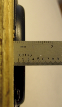
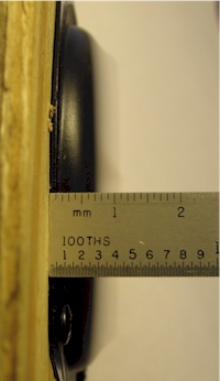
Figure 4-2: ND90 Impedance and Thiele/Small Parameters measured using the WT3 Woofer Tester Measuring Xmax As part of the driver qualification testing I especially wanted to verify the driver's Xmax as this was a critical parameter for allowing the system to achieve adequate acoustic output in the lowest octaves. Because of the difficulty in measuring Xmax I decided to perform a direct observation of the excursion with the driver was operating at 50 Hz and distortion increasing to 10% 3rd harmonic (i.e. 3rd harmonic 20 dB below the fundamental). I set up my camera to catch the actual excursion as the system was operated at the excursion limit.
The
baseline displacement is 6mm as seen in the Figure
4-3 (above) at the left. Operating at
10% 3rd harmonic the peak excursion is seen to reach the 11mm
mark in the right photo. That equates to a peak excursion of 5mm at 50 Hz as
the 3rd harmonic reaches 10%. From this observation I’d say the
driver has an effective Xmax of 5mm. At no point did the driver bottom out
or otherwise appear to reach any hard mechanical limit in the course of my
testing. Compared to most of the speakers I’ve evaluated over the years the
ND90 performs exceptionally well up to and even beyond the limits of its
excursion capability. Frequency Response I measured the frequency response of an individual ND90-8 driver using nearfield and ground plane methods. The nearfield measurement method provides a very accurate response up to about 3kHz for this size driver. This upper limit on the nearfield data is a limitation of the nearfield measurement method itself as described by Don Keele. [Ref. 4-1] The nearfield measurement was very smooth and highly repeatable so that no averaging or smoothing were required. Figure 4-4 shows a single unsmoothed nearfield measured response. Note that the nearfield response is equivalent (in shape) to a farfield half-space response. That is, it exhibits no diffraction loss as would normally be seen in the farfield measurement with the enclosure in free space.
The ground plane frequency response was measured at 1W (2.83 Vrms), 1 meter outdoors about 15 feet from my house. The ground plane measurement is equivalent to a farfield measurement with two identical speakers placed side-by-side (or one over the other). My ground plane measurement setup was not ideal and definitely included some local reflections. Still, it does give a good picture of the overall frequency response of an individual driver in a small enclosure in free space. The measurement seen below includes the effect of diffraction loss which appears as a 6 dB decrease in response below 2 kHz. For more on diffraction loss see my Tech Topic on the subject.
The ground plane response shown at the top of Figure 4-5 is an average of the 5 responses below with (slight) 1/6th octave smoothing. The five responses were obtained by varying the outdoor measurement geometry slightly (rotation and/or translation) between measurements in an attempt to average out variations due to reflections from the side of the house. In order to create a frequency response that best represents the response of the ND90 I combined the nearfield response below 2 kHz with the ground plane response above 2 kHz to get the hybrid response shown in Figure 4-6. This response is representative of the response of the driver in a small closed box with a half-space acoustic load. Note that these frequency responses are displayed in relatively high resolution with minor divisions equal to just 1 dB.
The raw response of the above closed box system is within +/- 2 dB from about 70 Hz to 8.5 kHz. The response is within +/- 4 dB from about 55 Hz to 20 kHz. It is the very wide frequency response range of the driver that makes this project possible. Here are links to text files containing the data for the above responses:
Distortion Performance Figures 4-7 through 4-10 show the distortion performance of a single ND90 driver in the 0.1 cubic foot test enclosure. The distortion was measured at 1 Watt (2.83 Vrms), 1 meter. We see the ND90 reproducing 100 Hz in Figure 4-7. The plot shows the 100Hz sine wave at a level of 80 dB SPL with higher harmonics (distortion components) all below 40 dB SPL. Note that the lines at 60, 120 and 680 Hz are components of ambient room noise...the notebook PC primarily. The 2nd harmonic at 200 Hz is at 38 dB SPL versus 80 dB SPL for the fundamental. This puts the 2nd harmonic 42 dB below the fundamental which equates to 0.8% second harmonic distortion. The 3rd harmonic at 300 Hz is down 44 dB from the fundamental for a 3rd harmonic distortion of 0.6%. The 5th harmonic is at -54 dB or 0.2%. The distortion components above the 5th harmonic vanish into the noise floor.
Next in Figure 4-8 we see the driver at 200 Hz. The 2nd harmonic at 400 Hz is at -51 dB or 0.3%. The 3rd harmonic, 600 Hz is at -55 dB or 0.18%. The 5th harmonic is at -57 dB or 0.14%.
The 500 Hz distortion performance is shown in Figure 4-9. The 2nd harmonic is at least 63 dB below the fundamental or .07% or lower. The 3rd harmonic at 1.5 kHz is at -55 dB or 0.18%. The 5th harmonic is at -59 dB or 0.11%.
The performance of the ND90 at 1 kHz is shown below in Figure 4-10 where we see that the dominant distortion component is the 3rd harmonic at -49 dB with respect to the fundamental or 0.35%. The 5th harmonic is at -55 dB or 0.18%.
The distortion measurements for the ND90 show a driver with less than 1% harmonic distortion at the 1 Watt drive level. No other hidden distortions were evident in the course of my distortion testing. These numbers confirm what my ear had already told me: this is a nice clean little driver with no audible distortions of any type. While healthy ND90s exhibit the low distortion shown above I did have one driver (out of 50) that "buzzed" and had to be replaced. For this reason when performing final assembly on the loudspeakers it is a good idea to quickly audition each driver with a low frequency tone (say 80 Hz) to identify any "buzzing" units before they are installed. In production environments a "rub and buzz" test is often performed on drivers as they are unpackaged and just before they are installed into a speaker system. Next: 5. Array Test Results |
|||
|
Measurement References [4-1] D.B. Keele Jr., "Low-Frequency Loudspeaker Assessment by Nearfield Sound-Pressure Measurement," J. Aud. Eng. Soc. Vol.22, p.154 (1974 March) |
|||
|
|
|
True
Audio Home Page | Catalog |
Tech
Topics | Audio Links |
Book
Store Your comments are welcome at webmaster@trueaudio.com |