|
|
Updated: Wednesday, 16 November 2011 |
|
|
|
Updated: Wednesday, 16 November 2011 |
|
|
The Murphy
Corner-Line-Array An Open Loudspeaker Design Project by John L. Murphy Physicist/Audio Engineer |
|
1. MCLA Project Home |
5. Array Test Results 6. Line References/Links |
7. Project Log 8. MCLA Discussion Thread |
|
|
2. Design Concepts |
|||
|
Loudspeakers in Rooms
Loudspeakers always seem to be at odds with the room in which they must
operate. In order to deal with this designers resort to all sorts of clever
tricks. We go to great lengths to either test our speakers in a anechoic
chamber or to take quasi-anechoic measurements with fancy test instruments
all in an attempt to show what the speaker should sound like...if it weren't
for that darn room. But like it or not, virtually all loudspeakers find
themselves playing into a room and competing with their own reflections for
the listeners attention. My new corner-line-array is an attempt to bring
some peace in the war between loudspeakers and rooms. Instead of fighting
the room or pretending it's not there, the corner-line-array design joins
the loudspeaker with the room in such a way that the performance of the
loudspeaker in the room is more predictable and repeatable than with
previous point, line or planar type loudspeakers. Image Analysis Image analysis is a powerful technique used in the field of acoustics to study reverberation and room reflections. In this analysis the walls of the room are considered to be mirrors and reflected images of sound sources can be readily located. Before proceeding let's review the image analysis method as it applies to loudspeakers in rooms. The famous acoustician/physicist Carl F. Eyring commented on the image method in 1930 as follows: "This necessary analysis is aided by the method of images. Just as a plane mirror produces an image of a source of light, so also will a reflecting wall with dimensions large as compared with the wave length of the sound wave produce the image of a source of sound. An image will be produced at each reflection. In a rectangular room, the source images will be discretely located through space. This infinity of image sources may replace the walls of the room, for they will produce an energy density at a point in the room just as if they were absent and the walls were present." [2-1] Here Eyring is saying explicitly that the image sound sources can be substituted for the room and the resulting sound field will be the same. The assembly of reflected images is exactly equivalent to the effect of the room. A sound source in a room is exactly equivalent to that same sound source in free space along with an infinite array of sound sources representing the mirror image reflections of the single sound source in the room. A rigorous mathematical foundation for the image method can be found in the 1978 paper by Allen and Berkley titled: "Image method for efficiently simulating small-room acoustics" [2-2] It is also worth mentioning that in 1957 the well known acoustician Richard V. Waterhouse also used the image method to analyze the effect of reflecting surfaces on sound sources. [2-3]
Floyd Toole in his recent (2008) book titled "Sound Reproduction, The
Acoustics and Psychoacoustics of Loudspeakers in Rooms" [2-4] writes: The simple rule of equal angles of incidence and reflection is shared with the field of optics, a sister field of acoustics falling under the fundamental science we call physics. This shared rule is why acoustical reflections are located in exactly the same positions as the visual images of the sound source that we would see if the walls were mirrored. In Figure 2-1 below we see an object reflected in a single mirror. If the object in front of the mirror were a sound source that sound source would have a reflected acoustic image at the same apparent location as the optical reflection. Placing the object against the mirror would result in the object and the image being back to back. The acoustic equivalent would be the difference between full-space and half-space loading (see my Tech Topic on Loudspeaker Spatial Loading for more on acoustic loading). The acoustic image located close to the sound source as a result of a reflecting surface boosts the sound level by 6 dB exactly as if a second sound source were placed next to the original in free space. These are different but compatible views of the same observed phenomena. See Refs. [2-1], [2-2] and [2-3] below for a entry points into the scientific literature on the image method in acoustics.
Now lets consider what happens when viewing an object in two mirrors placed at 90 degrees to one another as in Figure 2-2 below.
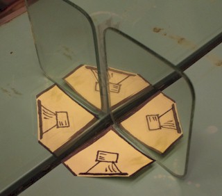
The object has picked up not just one, but two more reflections. Reflection 1 is the original reflection. Reflection 2 is a new reflection from the second mirror that corresponds to reflection 1 in the first mirror. Reflection 3 always falls in the corner and is the reflection of reflection 1 and reflection 2 as seen by the opposite mirror. This 3rd reflection is best understood by doing the experiment with two mirrors, and if you actually do the experiment you will see the original object along with 3 reflected images. As the object is moved nearer to the corner all 3 images move closer together to give the appearance of four tightly spaced objects. If the object is a sound source then it will also have three reflected images when placed close to an acoustically reflective surface (such as a wall of a room). This is what happens when a speaker is loaded by a quarter-space load as at the intersection of two walls of a room. Compared to the original speaker in free space the sound level is increased by 12 dB (6 dB for the first reflection and another 6 dB as the number of sound sources is doubled from 2 to 4). You can view this problem two different ways. First, we can view it as a speaker with different spatial loads. Alternately, and just as valid, we can view it as multiple speakers in free space. For the purposes of the present discussion I will continue to use the acoustic image model. In Figure 2-3 below I show a simple example with two mirrors placed at right angles similar to two walls of a room. You can see the small hand mirror I placed at 90 degrees to the larger mirror. There is only one paper speaker mockup in the photo but you can clearly see all four speakers around the faces of the overall octagon formation. The acoustic images will appear in the same locations as seen here.
Figure 2-3: This Photograph Shows a Single Drawing of a Speaker Along With Three Reflections in Two Perpendicular Mirrors The View From The Top Consider again the simple case of the object reflected in a single mirror. The view from above would be as seen in Figure 2-4 below.
Now, consider the top view for the two mirror case shown in Figure 2-5 below. In this figure I have shaded the reflections lighter to indicate that they are slightly weakened by the absorption of the walls...sort of like a dirty mirror. Because reflection 3 is a second order reflection (that is, a reflection of a reflection) it is shown even more dim than the first order reflections. It doesn't matter whether the reflected images are optical or acoustic as their positions are the same.
Notice that moving the object all the way into the corner results in the four images coming together in a tight pattern as seen in Figure 2-6 below.
Back to the Room In a normal home listening room the sound reflected from the walls, floor and ceiling creates reflected sound images in the same way the optical images appear in the mirrors in the discussion above. "Ray Tracing" is a method that has long been used in the study of both optics and acoustics. Ray tracing allows us to precisely locate reflected images using a simple form of geometric analysis. Rays follow this rule for reflection: the angle of reflection is equal to the angle of incidence. Let's examine how a single reflected image is created in a listening room. In Figure 2-7 below we see "rays" of sound leaving a sound source and arriving at the listener by way of two paths. The ray A-B from sound source A to listener B follows the direct path. There is only one location on the side wall where a reflection occurs such that the incident and reflection angles are equal and that passes through the listening position B. That reflection path is through point C. The sound ray A-C propagates from source A to reflection point C and is then reflected from the wall as ray C-B from the reflection point to the listener. The presence of the wall creates a very real reflected image at D, just as if the wall were absent and a second sound source were added at that location. The ear is tricked into hearing the sound that arrives via ray path A-C-B just as if the path were straightened out and arrived via the phantom path D-B. Just as the eye sees the reflections in the mirrors in the previous discussion, so too does the ear hear sound appearing to arrive from the location of the reflected image behind the wall. From an energy point of view, we would say that the wall redirects sound energy that would have gone unheard toward the listener thereby creating a higher sound level at the listeners position than if the wall were absent.
Once we see how a single reflected image is formed we might notice that in Figure 2-7 above there would be additional images from the front wall and corner reflections just as in the optical cases we saw in Figures 2-5 and 2-6. The optical and acoustical examples are wonderfully analogous cases where strict mathematical analogies can be applied. In Figure 2-8 we see the additional sound images E and F that in addition to image D would be created by the two walls shown. The added rays show the path from A to B via a precisely located reflection from the front wall to create image E. Rays to define the corner image are not shown but would go through the corner of the room. Once the room is enclosed with all six reflecting surfaces (four walls plus ceiling and floor) the number of reflections is increased to infinity giving rise to the sound of reverberation in the room. The finite absorption of the surfaces of the room attenuates the images as they repeat causing the reverberation to eventually decay to inaudibility. Once aware of the reflected images we can begin to take control of the "house of mirrors" game that inevitably ensues when we experiment with loudspeaker placement in rooms. My solution here is to merge the reflections with the original sound source by moving the sound source (line array) into the corner. Moving all the sound sources into a tight group increases the upper frequency limit for their coherent summation and keeps arrival times tightly clustered well enough for the multiple sources to fuse into a single perceived sound source. Moved out of the corner the array would create more widely separated images which would have a wider spread in arrival times and would be in danger of not fusing into a single perceived sound source.
Figure 2-9 shows a pair of point source radiators located against the front wall of the listening room along with their first few reflected acoustic images in the floor, ceiling and side walls. Only the first one or two reflections are shown but the array of images actually continues to infinity in all directions...just as regular optical mirrors would show if each wall were mirrored. Each successive reflection grows weaker due to the finite sound absorption of the walls. The listener hears the speakers directly along with all the reflected images. The delay of each image is determined by its path length to the listener. The shortest path to the listeners ears is the direct path from the speakers. Those reflections that follow within 20 -30 milliseconds of the direct sound more or less fuse together into a single perceived sound. Those reflections arriving after 30 milliseconds or so are heard as early reflections and reverberation. As you move away from the speakers and toward the rear of the room the direct sound from the speakers falls compared to the total combined energy of the reflections. Note that the SPL falloff rate for each image is the same as for the direct sound: 6 dB per doubling of distance.
My response to questions about an array's "comb filtering" is to point out that our human hearing systems are not sensitive to this particular type of frequency coloration. Besides, point source loudspeakers suffer the same comb filtering effects when used in rooms and/or in multiples, that is, in normal use. So comb filtering results whenever any speaker is used in a normal residential environment, if is not something that happens only with arrays. My goal with the corner-line-array is to include the inevitable room reflections in the design from the start in order to achieve a frequency response that is more consistent throughout the room and from room to room. I would hope that if you reproduce the MCLA's in your room that you would achieve very nearly the same frequency response as I achieve in my own reference system. This is rarely the case with point source speakers for which there is no standardized room location. Lines in the Room Now consider what happens when we place a line array loudspeaker in a room where the line array spans from floor to ceiling. Note the ceiling and floor reflections shown in Figure 2-10. The first order reflections TRIPLE the effective length of the array. Including the second order reflections we see the height of the array increased FIVE FOLD over the actual speaker. A seven foot long array is reflected into a 35 foot array by consideration of just the first two reflections. A seven foot array of 24 speakers is transformed into a 35 foot array with 120 sound sources based on two reflections. In reality the higher order reflections are significant and the array is effectively longer with even more sound sources. In a perfectly reflective room the lines would extend to infinity giving the room an infinite reverberation time. The finite reverberation time of real rooms indicates that the reflections actually fade to inaudibility as they extend toward infinity in all directions. The combination of direct and reflected sound sources actually forms a very long array with the output progressively more tapered toward each end.
Fun With Mirrors Now let's look at the view from above when a line array is placed in the corner of the room. Figure 2-11 shows the corner-line-array placed in the corner of a room. In light of the front and side wall reflections we now have four arrays tightly packed into the corner.
I custom shaped the enclosure to fit in the corner in such a way that it joins with its reflections to form a tight octagonal cluster of four line arrays. If you imagine moving the array out of the corner you would see all four arrays moving apart. Bringing the array into the corner causes the front and side wall images to merge with the real line to form a very real acoustic cluster of four arrays extending about 16 feet above and below the actual arrays. Instead of having one driver every 3.5 inches we actually have four drivers for every 3.5 inches of height. You could argue that from the listening area we now effectively have an average driver spacing of less than 1 inch. A single physical array near 8 feet in length with 24 drivers integrates with the room to form a new acoustic system of four clustered arrays extending another 16 feet beyond the ceiling and floor and tapering off toward infinity. Figure 2-12 shows a 3D view of one array with its corner reflections and repeating floor reflection.
This net acoustic system now has the power of not just 24 three inch radiators but a total of N = 5 x ( 24 x 4) = 480 radiators. That's for just one line. With two MCLAs in the room you effectively have about 1000 sound sources configured as long octagonal tubes with speakers on 4 faces of the octagon. A 3D view of two arrays in a room along with corner reflections and two ceiling and floor reflections is shown in Figure 2-13. If you wanted to reproduce the MCLA system in free space outdoors that is exactly how you would construct it...using about 1000 drivers. But remember that the ceiling and floor reflections don't actually stop at just two reflections as shown but rather continue to infinity in each direction fading out as they go. A simple array of 24 drivers is reflected into a monstrous acoustic tower when carefully placed in the corner of a room. As if this is not enough to boggle the mind, each of these two "towers" has additional repeating reflections in the side walls and rear walls (not shown).
The 3D drawings here were created in Google SketchUp 7 (free 3D drawing software). Here is my SketchUp file if you want to take a look: MCLA 3D.skp Simulating arrays with up to 24 drivers reveals that the net frequency response consistently improves as the number of drivers is increased and their spacing reduced. The simulated response for 24 drivers averaged over the listening area is quite excellent so I have every reason to expect that a simulation of 480 drivers (one array with first reflections) would prove to be very much smoother throughout the listening area...just as I measure. The large number of sources and their tight spacing very effectively resolve many of the issues that are raised concerning line array loudspeakers. By "managing" the room reflections instead of ignoring them, the MCLA loudspeaker system can achieve a frequency response that has a very good chance of being consistent from room to room. I look forward to seeing reports and measurements from those of you who build the MCLA. Here, just for fun, in Figure 2-14 is another 3D view from outside the front top-left corner of the room looking toward the front bottom-right corner. A more evolved design might move toward closing the gap by making the array length more closely match the exact floor to ceiling distance.
The corner-line-array when located in the room as prescribed provides an overall acoustic playback system that is generally superior to the typical point-source playback system (Figure 2-9 above). The widely spaced images of the point-source playback system produce a colored frequency response that is unique to each room and varies with speaker position in the room making consistent performance almost impossible. The corner-line-array with its standard speaker placement and well managed reflections appears, in my opinion, to be a superior solution to the overall application of loudspeaker playback systems in home environments. Those who might still be concerned about "comb filtering" effects are encouraged to reconsider their concerns in light of the image analysis and measured data presented here for the corner line array. Comb filtering is inescapable when any speaker is placed in a typical residential listening room due to the multi-path reflections always present. The typical placement of point source, line or planar speakers in our listening rooms results in especially bad comb filtering because the reflected images are so distant from the sound source. Ultimately what really matters in a high performance audio monitoring system is the frequency response that the system achieves in-room at the listening area, not the anechoic response that WOULD occur IF the system were auditioned in an anechoic chamber...in mono. References: [2-1] C.F. Eyring, "Reverberation Time in 'Dead' Rooms," J. Acoust. Soc. Am., (1930, Jan.). [2-4] Floyd D. Toole, "Sound Reproduction, The Acoustics and Psychoacoustics of Loudspeakers and Rooms.", Focal Press, 2008
Next : 3. MCLA Project Details |
|||
|
|
|
True
Audio Home Page | Catalog |
Tech
Topics | Audio Links |
Book
Store Your comments are welcome at webmaster@trueaudio.com |